

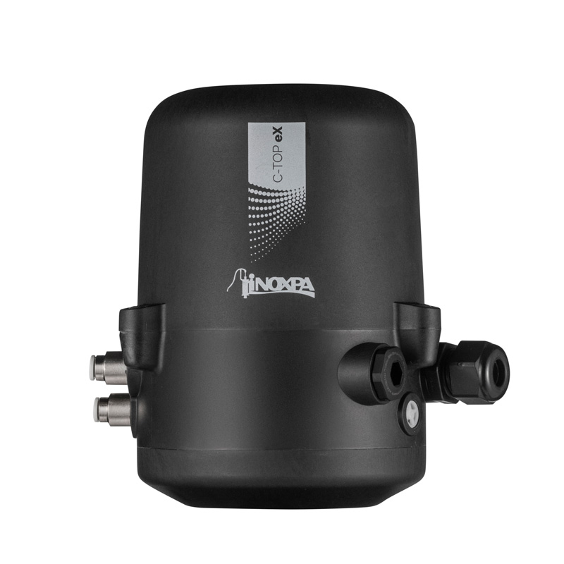
The C-TOP eX is a control unit that fits every INOXPA actuator and automates pneumatically operated process valves located in potentially explosive areas in the food, beverage, chemical, and pharmaceutical industries, among others.
C-TOP eX 反馈控制单元
请求信息
C-TOP eX 反馈控制单元
操作原理
The control head has a sensor system with NAMUR feedback using an LED indicator and low voltage solenoid valves, which are suitable for connection to an electrical or intrinsic safety barrier, and to a PLC with a digital interface.
External signals activate one to three solenoid valves, which control and act on the valve actuator. At the same time, inductive sensors detect the position of the valve actuator using the metal target installed on the actuator shaft.
The LED indicator will turn off once the set position is detected, sending the corresponding electrical signal through the electrical barrier to the PLC.
设计和特征
The C-TOP eX is easy to fit onto the top of the valve actuator.
Quick and simple configuration.
Detection through feedback from NAMUR inductive sensors.
These sensors have an LED indicator for visual verification of their detection status.
材料
Plastic parts PA6 + FV
Screws A2
Seals NBR
Pneumatic connections nickel brass
Environment
Outdoor use A location away from direct sunlight or UV sources
Storage temperature -20ºC to 50ºC
Ambient temperature -5ºC to 50ºC
Relative humidity 80% up to 31ºC, decreasing to 50% at 40ºC
Maximum altitude 2000 m
Overvoltage category II
Pollution degree 2
Degree of protection IP65/67
Control unit
Stroke ≤ 70 mm
Maximum actuator shaft diameter 22 mm
Adapter shaft diameter 6 mm
Type of fitting: screws
Fluid filtered compressed air, filtration degree 40 μm with or without lubrication
NAMUR sensor Solenoid valves
Maximum input voltage (Ui) 15 V 28 V
Maximum input current (Ii) 50 mA 115 mA
Maximum input power (Pi) 0.12 W 0.8 W
Maximum self-inductance (Li) 110 μH 0 μH
Maximum self-capacitance (Ci) 145 nF 0 nF
Inductive sensor
Feed NAMUR
Output function normally closed
Detection range 2 mm ± 10%
Nominal voltage DC 8.2 V
Pick up voltage DC 7.5 to 30 V (if using a safe area)
Status indication LED, red (internal)
Measuring method electromagnetic induction
Solenoid valves
Amount 0 - 3
Type 3/2-way, normally closed with a manual latch
Pressure range 3 - 7 bar
Supply voltage 24 V DC ± 10%
Power consumption 0.5 W
文件
操作原理
The control head has a sensor system with NAMUR feedback using an LED indicator and low voltage solenoid valves, which are suitable for connection to an electrical or intrinsic safety barrier, and to a PLC with a digital interface.
External signals activate one to three solenoid valves, which control and act on the valve actuator. At the same time, inductive sensors detect the position of the valve actuator using the metal target installed on the actuator shaft.
The LED indicator will turn off once the set position is detected, sending the corresponding electrical signal through the electrical barrier to the PLC.
材料 and 选择
Plastic parts PA6 + FV
Screws A2
Seals NBR
Pneumatic connections nickel brass
Environment
Outdoor use A location away from direct sunlight or UV sources
Storage temperature -20ºC to 50ºC
Ambient temperature -5ºC to 50ºC
Relative humidity 80% up to 31ºC, decreasing to 50% at 40ºC
Maximum altitude 2000 m
Overvoltage category II
Pollution degree 2
Degree of protection IP65/67
Control unit
Stroke ≤ 70 mm
Maximum actuator shaft diameter 22 mm
Adapter shaft diameter 6 mm
Type of fitting: screws
Fluid filtered compressed air, filtration degree 40 μm with or without lubrication
NAMUR sensor Solenoid valves
Maximum input voltage (Ui) 15 V 28 V
Maximum input current (Ii) 50 mA 115 mA
Maximum input power (Pi) 0.12 W 0.8 W
Maximum self-inductance (Li) 110 μH 0 μH
Maximum self-capacitance (Ci) 145 nF 0 nF
Inductive sensor
Feed NAMUR
Output function normally closed
Detection range 2 mm ± 10%
Nominal voltage DC 8.2 V
Pick up voltage DC 7.5 to 30 V (if using a safe area)
Status indication LED, red (internal)
Measuring method electromagnetic induction
Solenoid valves
Amount 0 - 3
Type 3/2-way, normally closed with a manual latch
Pressure range 3 - 7 bar
Supply voltage 24 V DC ± 10%
Power consumption 0.5 W
文件
| Document № | 10.428.33.01ES |
| File type | |
|
|
| Document № | 10.428.33.01EN |
| File type | |
|
|
| Document № | 10.428.33.01FR |
| File type | |
|
|
| Document № | 10.428.33.01RU |
| File type | |
|
|
| Document № | 10.428.30.04MU |
| File type | |
|
|
| Document № | 10.428.30.01ES |
| File type | |
|
|
| Document № | 10.428.30.01EN |
| File type | |
|
|
| Document № | 10.428.30.01FR |
| File type | |
|
|
| Document № | 10.428.30.01RU |
| File type | |
|
|
相关产品
-
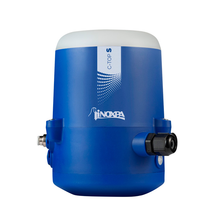
C-TOP S
反馈控制单元
The C-TOP S control unit can adapt to any INOXPA actuator, and both efficiently and individually...
-
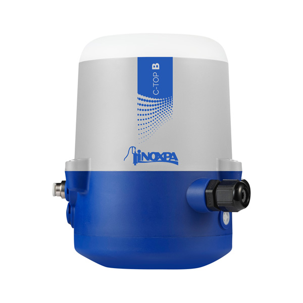
C-TOP B
反馈控制单元
The C-TOP B control unit can adapt to any INOXPA actuator and both efficiently and individually...
-
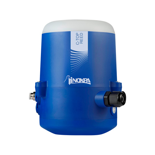
C-TOP REED
反馈控制单元
The C-TOP Reed control unit can adapt to any INOXPA actuator, and both efficiently and...

